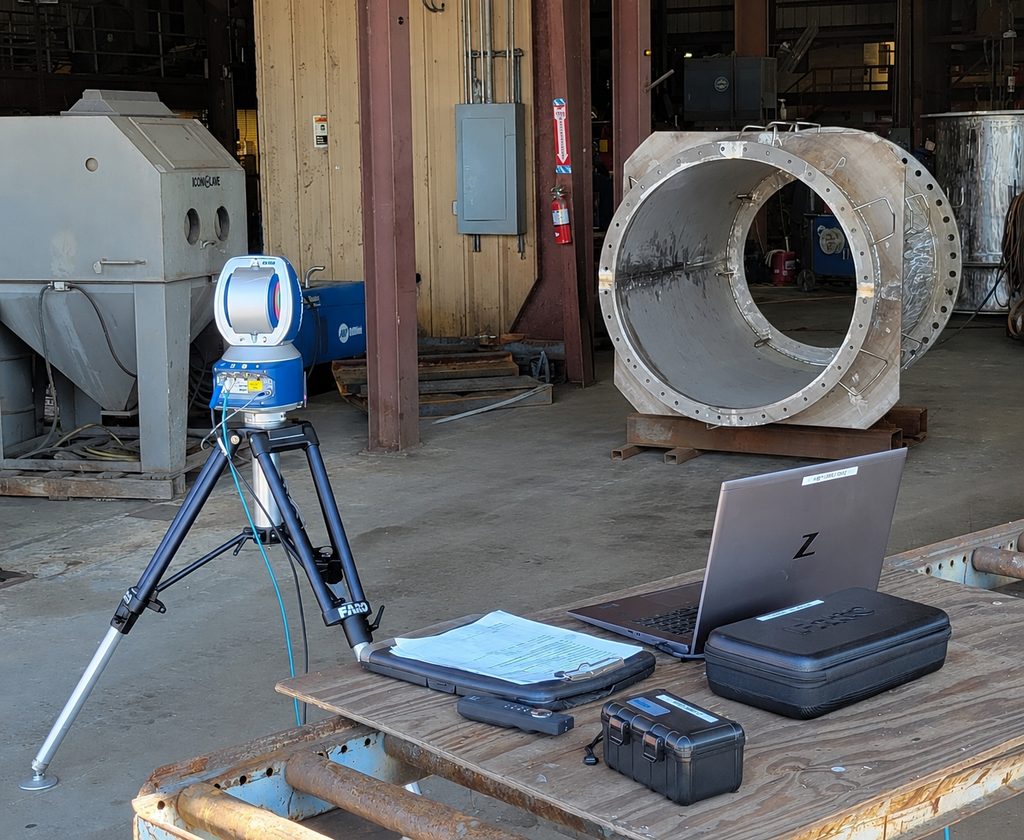
Large marine and industrial components cannot always be evaluated through individual dimensions alone. A bore may meet its diameter requirement but not share the intended centerline. A flange may be flat but sit at the wrong angle to its mating surface. Components may also fall within tolerance individually while creating a dimensional problem once assembled.
3D Measurements allow engineers and technicians to evaluate these relationships within a shared coordinate system. Measurement points collected from bores, flanges, machinery and structural references can be used to establish planes, centerlines and axes. From there, we can assess alignment, flatness, parallelism, perpendicularity, angularity, runout and distances between critical features.
The process typically includes reviewing the work area, selecting appropriate equipment locations, completing thermal compensation and field calibration, establishing reference points and collecting data directly from the features being evaluated. The collected points are then organized into meaningful geometric references rather than treated as isolated measurements.

Commercial Marine: Evaluating Azimuth Thruster Geometry
Following a grounding, the port and starboard azimuth drives on a commercial tug were removed and disassembled for inspection. We performed 3D Measurements on both the vessel-side hull mating flanges and the individually staged drive components.
The scope included drive cones, gearbox mounting flanges, bell housings, stems and a lower gearbox housing. Surfaces were evaluated for flatness, parallelism and perpendicularity, while bores and cylindrical features were measured for diameter and runout.
The important takeaway is that measuring both the removable machinery and the vessel interfaces helps determine where a geometric change has occurred. We can distinguish between deformation within a component and a dimensional issue affecting the hull-side mounting structure.

Industrial: Measuring Components Before and After Assembly
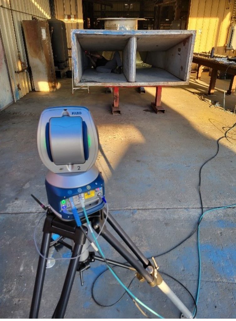
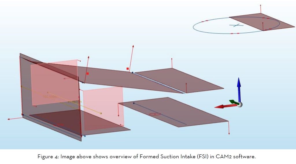
For an industrial formed suction intake and discharge column, 3D Measurements were performed on the components individually and again as a complete assembly before delivery.
Measurements included seat-ring bolt-hole locations, centerline distances, stiffener dimensions, bolt-hole diameters, distances between anti-rotation ribs, and seat-ring inside and outside diameters. The collected data was used to establish coordinate systems, planes, angles, flatness and distances.
This comparison is important because two components can meet their individual dimensional requirements but still develop an issue when assembled. Interface geometry, fabrication variation and accumulated tolerances can all affect the final configuration. Measuring both conditions provides a clearer picture of whether the completed assembly reflects the intended geometry.
Yacht: Checking Bore and Propulsion Alignment
On a single-screw motor yacht, the vessel was hauled and its running gear removed before an alignment assessment was completed.
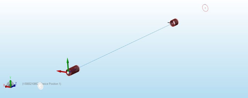
Measurement points were collected from the forward and aft ends of the stern tubes and the reduction-gear output flange. The data was then used to establish reference lines and determine the relationship between the installed bore geometry and the propulsion machinery.
The driveline was evaluated using multiple lines of sight, including references formed through the stern-tube seal housing and bearing bores. Bearing angularities were also measured.
The key takeaway is that 3D Measurements can use the stern-tube bores, seal housing and reduction-gear flange as shared references to help determine whether an alignment issue originates at the gear, the bearing bores or the relationship between those components.
Converting Measurements Into Better Decisions
The value of 3D Measurements is in its ability to turn those points into usable planes, axes and centerlines that answer a specific engineering question.
Across commercial vessels, industrial machinery and yachts, this technology provides a clearer understanding of how critical features relate to one another. That information can support machining, repair, assembly and alignment decisions before equipment is returned to service.
Need Accurate Data Before the Next Step?
AME provides 3D Measurement services for marine and industrial applications, including machinery and driveline alignment, bore assessments, geometric verification and dimensional inspections. Whether the goal is to support machining, confirm an installation or better understand an alignment issue, our team can develop a measurement plan around the specific equipment and conditions involved.
Visit AMESOLUTIONS.COM to learn more or discuss an upcoming project.